Well, if you look at the formal description, it will say “Formula Kentucky is the University of Kentucky’s Formula SAE Team. We are a student-operated organization whose goal is to engineer and fabricate a small formula-style open-wheeled race car. Our current focus is on the testing of our latest car, FK05, which competed at FSAE Michigan in May of 2023, and the development of our newest car, FK06.”
What is it?
Even though the above description may be accurate, it’s much more than just building an FSAE vehicle yearly. This club encapsulates the trials and tribulations of designing a complex machine from scratch. In every subsystem, there is a group of individuals dedicating their scarce extra time to design the most high-quality vehicle we can. Through hundreds of iterations and many long days spent optimizing a part using FEA, there is no lack of hard work. However, through this difficult task, many of the people within this club grow closer together and become much more than just club team members. Participation in this student organization has instilled in me the belief that collective dedication can overcome any obstacle, even in the absence of a clear solution.
What is it truly?
What have I contributed?
I joined the team in the fall of 2022, my sophomore year. Jumping into this team I was not sure exactly what to expect. I knew one thing; I liked cars. It just so happens when you get a group of students designing a race car, they just so happen to also like cars. I joined the suspension subsystem where I began to learn about the vehicle dynamics and how all the parts integrated.
After getting my feet wet within the club and understanding how the design phase integrated with the manufacturing phase, I received my first real project. That project was designing FK06’s rear rocker arms.
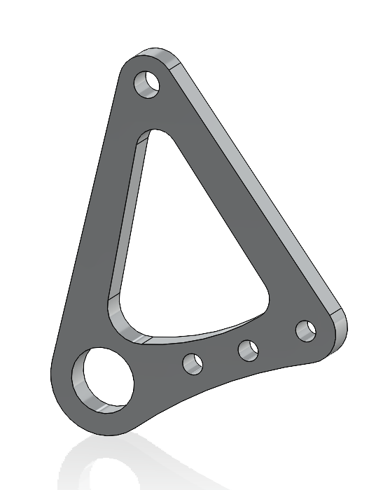
A rocker arm (in theory) is a relatively simplistic part of a suspension system. The rocker arm typically has one main function, translating the force from the wheel, via pushrod, into the shock/spring setup. Our rocker has 4 main mounting locations; the shock/spring, pushrod, antiroll bar, and chassis bearing mount. As shown, you can see each location marked in order.
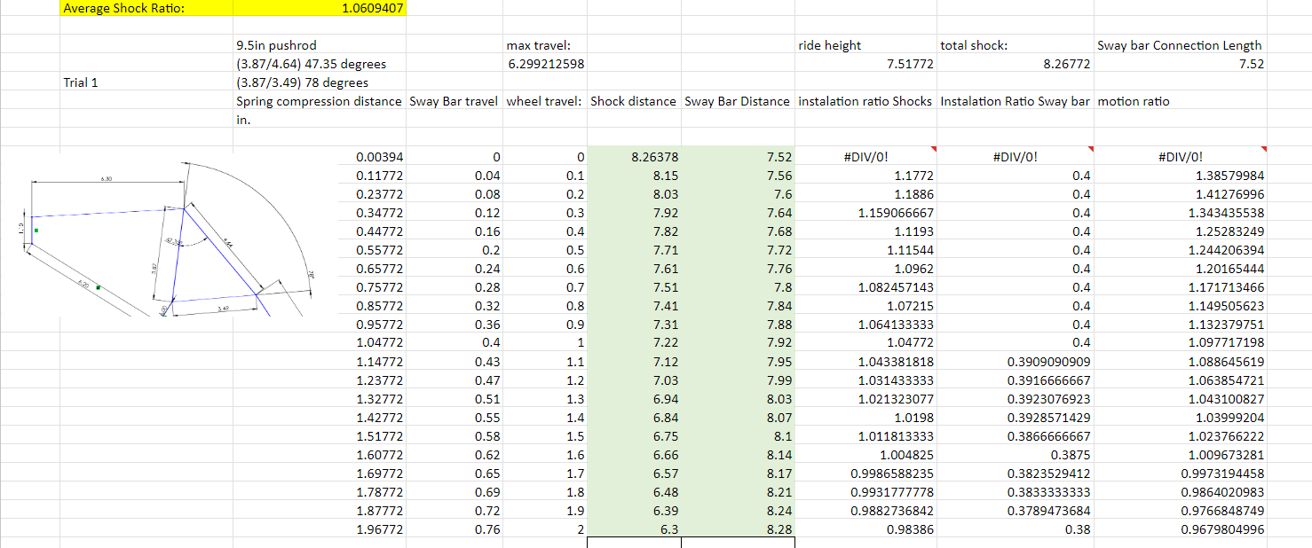
Well, that’s easy right? like I said, in theory. The real “issues” come from optimizing the ratio between the articulation of the wheel travel (vertically) and the compression of the spring. Our goal was to have a 1:1 ratio. As shown to the right, this is the sketch that I created of all the suspension components and how they interact. Since the entire system is dynamic, the ratio changes throughout the cyclic motion of the suspension travel. After many (hundreds) of iterations of all the different variables at play, I came to a final design. Thanks to my partner throughout this process, Ethan Smith, for creating an Excel spreadsheet to to these calculations for me.
After coming to general Measurements that I was pleased with, I needed to run FEA. This was my first year of seeing how to use FEA and interpret the data. After meeting with our team’s faculty lead, Tom Henninger, many times he showed me how to properly constrain and interpret the output. As I have learned, the output is only good as your data that is put in. After doing many hand calculations to find the maximum force acting on the pushrod and other components, I came to a set of input forces that I was pleased with. As shown, this is the final FEA with max loading under full deceleration.


